Blade Inspection by Physical Digital
Estimated reading time 3 minutes
Physical Digital uses the industry-leading GOM 3D optical scanning systems which are ideally suited to turbine blade inspection and analysis. Where accuracy, repeatability and traceability matter, the globally-respected 3D measurement systems provide a complete solution for turbine blade inspection, whether for power generation, aerospace or related sectors.
High resolution capture of scan data
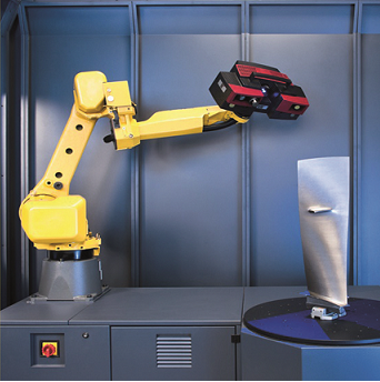
GOM’s ATOS III Scan blue light fringe projection technology precisely and accurately captures high resolution scan data of the blade. Twin cameras capture the fringe pattern which is projected onto the blade by a projector. Once the data has been captured, the inspection back to CAD is quick and simple to achieve using ATOS Professional software.
Batch inspection of blades using automated 3D scanning cell
If you only have a few blades, you can send them to our dedicated sites in Surrey or the West Midlands for analysis and inspection. However, if you have a large batch of blades, we can offer an even more resource-effective solution in the form of an automated 3D measurement facility. Using 3D non-contact scanning, batch inspection of a large number of turbine blades provides crucial insight into manufacturing stability. Physical Digital’s automated measurement cell, the ScanBox 5120, allows for the fast, accurate batch inspection of turbine blades, whether embedded in our customers’ sites or inspected at our West Midlands automated 3D scanning facility. Batch inspection provides information on accuracy and repeatability and informs the understanding of process variations.
Alignment and inspection criteria
For each blade inspection project, the alignment and inspection criteria varies vastly. Using the decades of industry experience at Physical Digital along with the intuitive and detailed GOM software, even the most demanding inspection can be completed.
Multiple alignments can be generated including 6 point nests, geometric features or virtual fixturing to ensure that the alignment is an accurate representation of the design drawings.
Potential elements for inspection include but are not limited to:
· Camber Line – Profile Mean Line
Skeleton Line
· Profile Centroid
· Profile Twist – Gaussian Fit
Chebyshev Fit
· Leading Profile Edge Points
· Trailing Profile Edge Points
· Leading Profile Edge Circle
· Trailing Profile Edge Circle
· Profile Chord Line- Axial Chord
Standard Chord
Bitangential Chord
Maximum Chord
Aerodynamic Chord
· Maximum Profile Thickness Circle
Distance
· Leading Edge Profile Thickness
· Trailing Edge Profile Thickness
Easy to interpret reports
Using GOM inspection software, Physical Digital provides printable, easy to interpret 2D reports, using industry-specific or customer-specific templates. One of the many advantages of the GOM optical measurement system is that it offers image mapping technology to provide real life visualisation of quality inspection results. This feature provides fast data interpretation, giving the real life context of the results, which enables non-technical personnel to understand the reports.
To bring verifiable accuracy to your blade quality inspection process, contact us today for a free quote. View our Youtube video which demonstrates the process of blade inspection using 3D scanning technology.