Tebis Version 4.0 Release 8 With More Automation for CAD/CAM Work
Estimated reading time 4 minutes
CAD/CAM and MES specialist Tebis has announced the latest release of Tebis Version 4.0. The new release offers many new and advanced functions including indexed collision avoidance, extended aggregate library, simplified feature scanner, advanced 5-axis simultaneous alternative milling, more convenient machine simulation and much more. For CAD side, Reverse engineering is now even easier and faster with more automation.
CAD – Reverse engineering
More automation and clear presentation of the results
As the basis for reverse engineering, you create a wire-frame model from digitised data, which in turn is used to create a surface model. The surface model can now be generated automatically and conveniently with the new Tebis Version 4.0 Release 8.
CAM – Automation
Better overview and clear operating structures in the revised feature scanner.
Features that are already connected to the component which were imported via data interfaces, or the part has already been scanned at an earlier time – are accounted for during scanning and don’t have to be inserted again.
The new “Auto” function is also very convenient: The component is completely scanned with no interruptions, and clearly evident features are automatically inserted. If several different features are possible for a machining operation, you can jump right to the appropriate areas after scanning and select the desired feature.
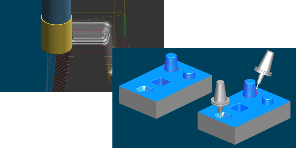
CAM – Data processing
Profile contours for turning can now be derived with absolute precision from the 3D component contour using the revised “Profile” function. Circles are also mapped one-to-one. The subsequent blanks are more precise with no need for design preparation of the profile contour.
CAM – Milling
Machining time is significantly reduced. The machine spindles are subject to lower loads due to machining in the axial direction. Side milling and downward machining can be easily combined, so you can fully benefit from the advantages of both strategies
Faster machining with indexed collision avoidance
The function for residual stock machining provides a new and highly convenient strategy for collision avoidance with indexed tilt determination: This strategy automatically detects and connects milling areas that can be machined collision-free with the same tilt direction. The corresponding tilt direction is also calculated. Areas that can’t be machined without collisions are deactivated and can be selected in the continuation job. Of course, you remain completely flexible and can also manually subdivide the milling areas as desired.
Shorter run times and fewer machine movements in 5-axis simultaneous avoidance milling
The function for 5-axis simultaneous avoidance milling has been comprehensively improved. Specific milling areas that can’t be machined collision-free in an NC job calculated using the collision avoidance.
5-axis simultaneous deburring, now also with tapered cutters
Edges that don’t lie on the same plane in space can now also be processed by automatic multi-axis simultaneous deburring with tapered cutters. You can also specifically select whether you want to machine the component in climb cut, conventional cut or lace cut mode. Machining of sharp edges and corners has also been optimized.
CAM – Drilling
Extended unit library enables complete automation of deep hole drilling
The new release provides variable drill bushes and drill bush holders as machine components in the unit library. All components of ultra-modern deep drilling machines can now be stored as digital twins in the system. This enables the highly automated generation of NC programs for 5-sided deep drill machining.
Integrated simulation
Integrated simulation ensures collision protection before NC output. Travel behaviour and switching of drill bushes and drill bush holders are simulated with absolute precision in the virtual CAM environment.
CAM – Machine technology
Quickly and easily create tool assemblies
You can now very easily determine the insert length for tool assemblies at the click of a button. A line at the diameter of the cutter is drawn parallel to the tool axis. The intersection point between this line and the shank contour yields the insert length.
CAM – Job planning
More collision checking in multiple setups
For components in multiple setups, the blanks for adjacent components are now also fully accounted for by collision checking with the CNC simulator.
Tebis (UK) Ltd
Tel: 02476 158178
Email: info-uk@tebis.com